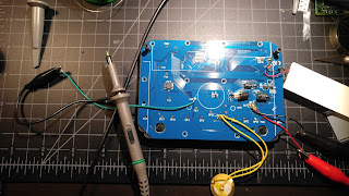
I have mostly concentrated my efforts in learning about reverse engineering software and software exploitation, so I figured I would branch out and try out some hardware hacking. I have no idea if I will be able to accomplish anything in this series of posts, but I am sure I will learn plenty of new things either way.
So the target of this project is the RecZone Password Safe Model 595.
This is a portable password database that seems to be pretty popular, at least on Amazon. I found it at a thrift store for $2.99 and figured it would be a cool project. Being a password bank, I'm going to assume that whoever designed this implemented some extra security measures in its design. Or maybe they didn't! You never know until you look!
Opening the case was simple. Just four screws in the back that hold the case together. The circuit board was held on with 10. The back of the board was simple. There are about a dozen or so small circular contacts placed on the board, which are clearly there for the manufacturer the test continuity and proper voltage levels. Each one has its own label, presumably to show what component it is assigned to. There is also one labeled as GND_ and one labeled as RST.
Poking around these contacts with my multimeter caused something to happen that I found interesting. When I put the ground probe on the contact labeled GND_ , and the tested the other contacts for the voltage levels, the piezo buzzer on the board would chirp. Some of the contacts read 3.3v and some hovered around 5v. There is also an IC on the left hand side that I am curious about.
Flipping the board over show the buttons, LCD and a couple COBs (Chip On Board).
Another thing that I found interesting was the way that the display comes in contact with the main board. Its not soldered on to the board, but its held in place with the pressure of the case. Here is a video showing it:
(Edit: After thinking about it, I realized that this might be a security feature. The traces on the board that come in contact with the LCD are looped back to other contacts on the LCD itself. So when you remove the screen, you break several circuits across the board. Plus the fact that the NVRAM and micro controller are underneath the screen kind of adds to my suspicion.)
Yeah yeah I know, I filmed it vertically.
Since there is so little to speak of on this board, the first thing I wanted to check out was that IC on the back of the board. Out came the oscilloscope. To make grounding the probe easier, I soldered a jumper wire to the contact labeled GND_ and grounded the probe to the other end.
For whatever reason, I had a hell of a time soldering the jumper wire to that contact, so please excuse the bad soldering job!
I could not find documentation on the IC. It was really small, but I was able to read the numbers on the top. It also seems to be "Globespan" brand.
25Q401
E49273
AE1128
Here is how I numbered the pins:
I probed the pins with both the scope and multimeter and found that Pin 4 is ground, and Pin 5 and Pin 6 both produce a signal. Pin 6 being significantly more active than Pin 5.
Pin 5:
Pin 6:
Well, that's it for now. In Part 2 I am hoping to capture these signals and try to understand what is happening here. (I just got a logic analyzer, so I will be starting the 2nd portion of this soon)


